Cable Commissioning: Post-Installation Testing Tips

Cable laying process

The main purpose of post installation cable testing is to check the cable and accessories for any defects that may have occurred during the installation process. Should a defect be found, the techniques of after installation testing help pinpoint the place of the fault and repair it.

The steps to be performed during post installation testing depend on the requirements to the newly installed cable or cable system; they may include the insulation and conductor resistance tests, sheath and conductor phase identification, cross bonding test, sequence impedance measurements, serving tests to check the quality of the outer sheath, sheath or screen resistance tests, and HV tests.

This post is going to discuss what needs to be taken care of in the process of a cable system commissioning process. While being quite obvious, these steps are often ignored to speed up the test procedures, but failure to follow them is likely to result in injuries to the personnel and significant time loss due to resulting cable system downtime in future.

Safety comes first

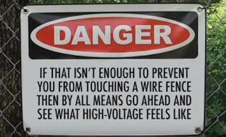
Danger! Electrical hazard
Since power cable testing carries electrical hazard, it is crucial to ensure the safety of the staff involved and to prevent unauthorized access to the testing site. The people present at in the testing area are to be limited to the testing personnel, who should have an appropriate line of communication. The testing site should be fenced off and warning signs should be put up.

In addition to safety reasons, it is important to stay clear of potential interruption as, for instance, the undesirable actions of observers might compromise the testing results and lengthen the time of testing.

Abide by the industry standards and regulations

Codes for cabling installation and testing have been written for a reason and are a good source of safe, reasonable and efficient practice during cable system commissioning.

Discipline and experience to achieve accurate results

Cables under test should be properly deegenergized, with earthing applied before and after testing cable ends should be insulated and the necessary precautions should be taken to avoid accidental contact. Care should be taken to remove the semiconducting material of the oversheath so as to prevent a flashover while testing the sheath.

No short cuts should be taken, with sufficient amount of time allocated to remove all the cross bondings in the link boxes.

Have the right cable testing equipment at hand

To avoid any interruptions and delays in the testing process, it is important to have on site testing systems for cable diagnosis and fault location matching the tested cable system specification. The testing equipment should be properly calibrated and used by experienced personnel.

Having found a fault, double check

In case a defect has been found, it is necessary to discharge the cable and check the integrity of all cable connections. Following this, the testing procedure is repeated, and if the defect is confirmed, a time domain reflectometer (TDR) can be used for prelocation in conjunction with a fault pinpointing system to locate the exact place of the defect.
Cable testing and commissioning

Discharge properly

The modern cable testing equipment is typically supplied with a discharge feature. However, a safe testing practice requires a manual discharge, so using a discharge rod at the end of the cable testing process should never be neglected.

Alexei Tiatiushkin
Marketing manager
KharkovEnergoPribor Ltd.
marketing@keppowertesting.uk
http://www.kep.ua

http://news.chivindo.com/367/cable-commissioning-post-installation-testing-tips.html

Comments

Popular posts from this blog

BT-BASIC commands used

8.10     Some of the most frequently used BT-BASIC commands used are: msi                               Changes default working directory. Mass storage is            Same as “msi” cat                               Catalogs (list)the node names in the specified directory.             get                               Brings the contents of a file into the system workspace.             load                             Same as “get”.             msi$                            Returns the directory pathname of the current working directory.             msi “..”                       Backs up one directory level.             findn                            Locates the next occurrence of the a given sting in the workspace. 8.11           If you wish to invoke the HP Board Graphics Viewer, type board graphics at the BT-BASIC command line and press the “ENTER” key on the keyboard. 8.12           A HP Board Graphics Viewer window should now appear

Perhitungan & Cara Merubah Kumparan Blender Dari 220 V Menjadi 12 V

          Seperti yang telah dijelaskan pada buku “menggulung motor listrik arus bolak-balik, servis peralatan listrik rumah tangga kelompok penggerak dan perbaikan peralatan listrik pertukangan”, bahwa motor penggerak yang digunakan pada perlatan listrik rumah tangga dan pertukangan seperti blender, mixer, bor tembak, gerinda dsb menggunakan jenis motor universal. Motor universal adalah jenis motor listrik yang dapat disuplai dengan sumber listrik arus bolak-balik (AC) dan arus searah (DC). Jadi peralatan-peralatan listrik rumah tangga dan pertukangan tersebut yang biasanya kita suplai dengan sumber listrik AC dari PLN atau Genset sebesar 220 V sebenarnya dapat juga kita suplai dengan sumber listrik DC yang tentunya tegangan juga harus sama yakni 220 V.           Yang menjadi permasalahan bagaimana kalau peralatan listrik rumah tangga atau pertukangan tersebut, sebagai contoh misalkan blender yang ingin digunakan atau dioperasikan pada tempat yang tidak terdapat sumber listrik PLN ata

BT-BASIC command line

8.8       At the BT-BASIC command line type the command  msi  and the directory path, then press the “ENTER” key on the keyboard.  Example:                   msi ‘/hp3070/boards/aspect/main’ 8.9       At the BT-BASIC command line type the command  get ‘testplan’ and press the   ENTER” key on the keyboard.  You should now see the body of the testplan file displayed in the work space of the BT-BASIC window. 8.10     Some of the most frequently used BT-BASIC commands used are:

Autodesk SketchBook Pro 2021 Full Version

BAGAS31 – Sesuai dengan namanya, Autodesk SketchBook Pro 2021 Full Version ini merupakan software digital sketching atau drawing terbaik yang bisa kamu gunakan. Pada versi terbaru kali ini, ada beberapa penambahan fitur yang sangat efektif. Dengan fitur baru tersebut, diharapkan mampu meningkatkan proses sketching maupun drawing kamu. Autodesk SketchBook sendiri sudah bisa kamu dapatkan secara gratis melalui website resminya. Namun untuk kamu yang mau download versi Autodesk Sketchbook Pro, maka bisa langsung download melalui link yang sudah saya sediakan di bawah ini. Download Autodesk SketchBook Pro 2021 Full Version Screenshot: System Requirements: Windows 10 2.5 – 2.9 GHz of Intel or AMD CPU 4 GB of Memory 256 MB Graphics card with OpenGL 2.0 support We recommend that you use a pressure-sensitive tablet and pen for basic features Download: Autodesk SketchBook Pro 2021 Full Version [ FileUp ][ Uptobox ][ UsersDrive ] Jamu Only [ FileUp ][ Uptob

Testhead

4.3         Testhead The testhead is that portion of the tester that supports the PIN, ASRU and Controller cards.   The testhead is divided into two BANKS and each BANK is divided into two MODULES, see figure 2 below.  Bank 1 contains modules 0 and 1, bank 2 contains modules 2 and 3.  The test fixtures are placed on the banks of the tester and locked down for board testing.  The testhead cards interface to the test fixture through the spring loaded pogo pin “nails” at the top edge on each of these card types. 4.4       Support Bay The support bay is a stand-alone cabinet that houses the power supplies for the Unit Under Test.  This bay also houses the test station power distribution unit and test station controller on earlier models. 4.5       Emergency Shutdown Switch The emergency shutdown switch is the large red button located at the lower left corner on the front of the testhead.  It turns off all AC power to the testhead, and is equivalent to turning off the m

Kelebihan dan Kekurangan Saluran Listrik Jenis Saluran Udara dan Saluran Bawah Tanah

Berdasarkan pemasangannya,   saluran distribusi dibagi menjadi dua kategori, yaitu : saluran udara (overhead line) merupakan sistem penyaluran tenaga listrik melalui kawat penghantar yang ditompang pada tiang listrik. Sedangkan saluran bawah tanah (underground cable) merupakan sistem penyaluran tenaga listrik melalui kabel-kabel yang ditanamkan di dalam tanah. 1.    Saluran Bawah Tanah (Underground Lines) Saluran distribusi yang menyalurkan energi listrik melalui kabel yang ditanam didalam tanah. Kategori saluran distribusi seperti ini adalah yang favorite untuk pemasangan di dalam kota, karena berada didalam tanah, maka tidak mengganggu keindahan kota dan juga tidak mudah terjadi gangguan akibat kondisi cuaca atau kondisi alam. Namun juga memilik kekurangan, yaitu mahalnya biaya investasi dan sulitnya menentukan titik gangguan dan perbaikannya. Kedua cara penyaluran memiliki keuntungan dan kerugian masing-masing. Keuntungan yang dapat diperoleh dari suatu jaringan bawah tanah adalah