At the end of the twentieth century in the world’s energy sector there was a clear trend for the integrated power systems to merge into wide area synchronous grids, both nationally and internationally. These synchronous electrical grids supplied energy to territories as big as the habitable land on the continents, and the numerous power suppliers contributing to the integrated power grids created a competitive international power supply market.
At that time in North America, Europe and Asia there were 7 high-capacity synchronous electrical grids that integrated power systems on vast territories with a population of over a billion people (see Table 1 for the details on these power grids).
These components are combined into a single synchronous area with high-capacity interconnections, first of all enabling to exchange electrical energy produced at the points where primary energy resources are obtained (water resources, biofuel) or generated at a nuclear power plant. Through the coordinated control of the integrated power grid development and operation, the utility sector has the ability to efficiently utilize primary energy sources, decrease energy loss during transmission, efficiently use reserve capacity, and generate electricity at the lowest reasonable cost.
When perturbations occur, the coordinated operation of the energy system components ensures mutual assistance and gives the possibility to speedily resume electricity supply after a system failure. Also, the competition of energy producers in the international power market promotes a lower electricity supply cost.
Behind the joint synchronous operation of the power grids that are part of transnational integrated power supply systems found in Europe and North America is the understanding that energy systems are interdependent, collaborate on the technical level and trust that every member follows the following set of rules:
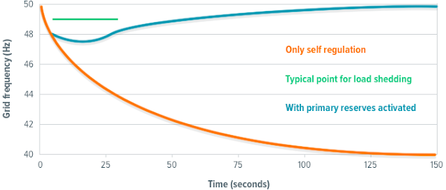
The primary control system uses turbine controllers to ensure the balance between the generated and consumed power. The primary control is triggered if the frequency level deviates from the standard by ± 20 mHz or more. This value is composed of the local frequency measurement accuracy (±10 mHz) and turbine controller insensitivity (±10 mHz). The capacity reserve for the primary frequency control should be 1 per cent of the maximum coverage, with the reserve activation time up to 30 sec (50 per cent in the first 15 sec, and 50 to 100 per cent linearly up to 30 sec).
Several international projects, facilitating energy cooperation in the Eurasian continent, aspire to create a common electrical power market, which would serve as the basis for a united transcontinental energy area.
 http://news.chivindo.com/378/the-development-of-transnational-and-transcontinental-synchronous-power-grids.html
At that time in North America, Europe and Asia there were 7 high-capacity synchronous electrical grids that integrated power systems on vast territories with a population of over a billion people (see Table 1 for the details on these power grids).
Economy of Scale as a Stimulus to Interconnections
The development of wide area synchronous grids was driven by economic considerations, as large power systems enabled the utility sector to provide higher quality electrical energy at a lower price. Wide area synchronous grids are typically made of integrated power grids or parts of national energy systems with their areas of operating control (system operators).These components are combined into a single synchronous area with high-capacity interconnections, first of all enabling to exchange electrical energy produced at the points where primary energy resources are obtained (water resources, biofuel) or generated at a nuclear power plant. Through the coordinated control of the integrated power grid development and operation, the utility sector has the ability to efficiently utilize primary energy sources, decrease energy loss during transmission, efficiently use reserve capacity, and generate electricity at the lowest reasonable cost.
When perturbations occur, the coordinated operation of the energy system components ensures mutual assistance and gives the possibility to speedily resume electricity supply after a system failure. Also, the competition of energy producers in the international power market promotes a lower electricity supply cost.
Table 1. Parameters of the largest energy systems
Location | Area, thousand square km | Yearly energy output, TW·h | Maximum load, GW | Installed capacity of power stations, GW |
Eastern USA and Eastern Canada | 5154 | 2950 | 508 | 722 |
Western USA, Western Canada and Mexico | 3108 | 874 | 112 | 158 |
Russia | 5100 | 791 | 127 | 192.6 |
Western and Central Europe | 2818 | 1558 | 251 | 414.2 |
Northern Europe | 1228 | 366.7 | 55 | 88.7 |
Western Japan | 173 | 556 | 78 | 97.8 |
Eastern Japan | 119 | 408 | 58 | 67.7 |
Basic Rules of Interconnected Operation within Integrated Power Grids
 |
Balance between electricity demand and consumption |
- in each country at any time there should be a balance between energy production and consumption;
- each partner should keep to the plans of power capacity exchange;
- none of the power systems can cause harm to the power systems of the other countries;
- each power system must maintain the frequency level;
- each power system must have a certain value of capacity reserve that is used for mutual assistance in case of a failure and for maintaining the frequency level;
- the power systems must fully cooperate in restoring normal operation as soon as possible.
The main task of each power system within an integrated power grid is to create favourable conditions for stable and reliable interconnected operation by taking primary, secondary, and tertiary measures to control the frequency and capacity.
Primary, Secondary, and Tertiary Control Systems
In the West European integrated power grid ENTSO-E, the European Network of Transmission System Operators, which includes 42 system operators from 35 European countries, the demands placed on the frequency and capacity control are very high.
 |
Primary control reserve activation |
All the members of integrated power grids are obliged to closely adhere to the regulations and standards established for a particular system, which ensures synchronous operation of an area without unified central control unit.
The main task of the secondary control is ensuring the set levels of capacity exchange between the power systems while maintaining the required frequency. Should perturbations occur in one of the power systems, after the primary control system mobilizes its active capacity reserve, the secondary control system must restore normal operation within 15 minutes. The capacity reserve for secondary control is to make up 5 to 10 per cent of the current load coverage. A minute’s reserve should correspond to the capacity of the largest unit of the grid.
The tertiary control system involves automatic and manual adjustment of the actual generator capacity or load. The reserves of the primary and secondary control systems are to be restored by activating the reserves of the tertiary control system, a process that is to commence within 15 minutes after directions on changing the capacity are issued. The size of the tertiary reserve in each power system should be large enough to maintain the required secondary reserve.
The cold or static reserve is to ensure the replacement of the highest-capacity generating unit that has gone out of order.
Another important aspect of the ENTSO-E requirements is maintaining the required grid reliability according to the N-1 criterion, which stipulates that, should any unit of the system go out of order (e.g. a generator, a transformer, a line), it must not endanger the safety of the integrated operation and must not cause cascading power outages.
Operational safety is ensured by complying with the requirements on maintaining the planned modes of real time operation, involving voltage adjustment and reactive power control. Voltage adjustment is done through primary, secondary, and tertiary voltage control.
Development of Major Transnational Power Grids
The West European integrated power grid ENTSO-E (formerly UCTE and UCPTE) was founded in 1951. In 1995 the integrated grid CENTREL, uniting the power systems of Poland, Czech Republic, Hungary and Slovakia, started interconnected operation with UCTE.
The creation of a modern Trans-European integrated power system, such as the synchronous grid ENTSO-E, results from a number of successfully connected national grids in line with the regulations and standards of the wide area synchronous grid. In the case of ENTSO-E this led to the establishment of one of the world’s most synchronous electrical energy areas, characterized by high stability and safety levels.
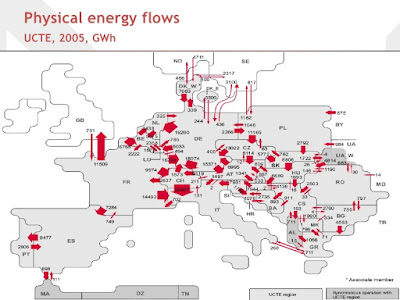
By the turn of the twenty first century the European continent housed 4 large-scale transnational integrated electricity systems:
- UCTE (including CENTREL), or the Western Synchronous Area;
- Great Britain and Northern Ireland;
- NORDEL, or the Northern Synchronous Area (the national grids of Sweden, Norway, Denmark, Finland and Iceland; the continental part of the Denmark’s national grid was interconnected with UCTE, and the Eastern part – with NORDEL);
- the Eastern integrated electricity system, or the Eastern Synchronous Area, which included most CIS countries and the integrated power systems of the Baltic states.
Perspectives on Expanding Wide Area Synchronous Grids
 |
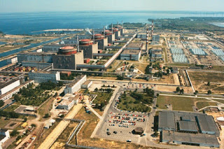
Nuclear power plant in Zaporizhia, Ukraine |
It is believed that the development of such projects in conjunction with strengthening the interconnections of ultra-high voltages within the integrated power grids will lead to the establishment of the high-capacity long-distance electricity grid Japan – China – Siberia – Kazakhstan – the European part of Russia – Ukraine – Eastern Europe – Western Europe. This would be a vital step towards creating a large-scale Eurasian synchronous electricity grid, a powerful component of the world’s electricity system.
Being considered is the Baltic ring project, which is to create a powerful integrated electricity grid comprising the national grids of the Scandinavian countries, Baltic states, Russia, Belarus, Poland, and Germany. In the West the Baltic ring is closed with submarine DC cable lines between Sweden and Germany, Norway and Germany, Sweden and Poland; in the East – with the lines of Russia, Belarus, and the Baltic states; in the North – with the high voltage DC link in Vyborg in the North-West of Russia and the lines of the Scandinavian countries. In the South the Baltic ring is closed with multi-substation DC transmission line Russia – Belarus – Poland – Germany, the capacity of which is 4000 MW.
Another project being considered is the transmission line Russia – Japan through the island of Sakhalin, through China and Korea, across the sea straits, and across the Bering strait to interconnect Russia and the USA.
Source (Russian language): http://energetika.in.ua
About KEP
KEP (KharkovEnergoPribor Ltd.) produces high voltage testing equipment, including portable testing instruments and cable test vans, for the world’s leading power engineering companies. The KEP’s product range includes solutions for cable tracing, cable diagnostics and fault locating, testing high voltage instruments and safety gear, and oil dielectric testing.
We at KEP believe that our main task is to translate the customer’s requirements into the top-quality product, combining cutting-edge technology with fundamental high voltage testing principles.
Alexei Tiatiushkin
Marketing manager
KharkovEnergoPribor Ltd.
marketing@keppowertesting.uk


Comments
Post a Comment