Basic PLC Ladder Programming Examples 22
Basic PLC Ladder Programming Training Examples for Beginners. Hi friends, here we are starting unique a series of Free Training on PLC Ladder Programming & tutorials. These PLC Ladder Programs are important to learn basics of Ladder programs.
Basic Program Designing Example 1:
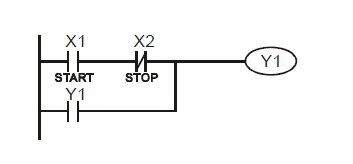
Start, Stop and Latched In some application occasions, we need to use the transient close/open buttons for the start and stop of an equipment. To maintain its continuous action, you have to design latched circuits. Example 1: Stop first latched circuit When the normally open contact X1 = On and the normally closed contact X2 = Off, Y1 will be On. If you make X2 = On at this time, Y1 will be Off. It is the reason why this is called “stop first”.
Example 2: Start first latched circuit
When the normally open contact X1 = On and the normally closed contact X2 = Off, Y1 will be On and latched. If you make X2 = On at this time, Y1 will continue to be On because of the latched contact. It is the reason why this is called “start first”.
Example 3: Latched circuit for SET and RST instructions
See the diagram in the right hand side for the latched circuit consist of RST and SET instructions. In the stop first diagram, RST is placed after SET. PLC executes the program from up to down, so the On/Off of Y1 will be determined upon its status in the end of the program. Therefore, when X1 and X2 are enabled at the same time, Y1 will be Off. It is the reason why this is called “stop first”. In the start first diagram, SET is placed after RST. When X1 and X2 are enabled at the same time, Y1 will be On. It is the reason why this is called “start first”.
Example 4: Power shutdown latched
The auxiliary relay M512 is latched (see instruction sheets for DVP series PLC MPU). The circuit can not only be latched when the power is on, but also keep the continuity of the original control when the power is shut down and switched on again.
Example 5: Conditional control
X1 and X3 enables and disables Y1; X2 and X4 enables and disables Y2, and all are latched. Due to that the normally open contact of Y1 is connected to the circuit of Y2 in series, Y1 becomes an AND condition for Y2. Therefore, only when Y1 is enabled can Y2 be enabled.
Example 6: Interlock control
If we serially connect the normally closed contact of Y2 in example 5 to the circuit of Y1 as an AND condition for Y1 (as the diagram in the left hand side), the circuit can not only make Y1 as the condition for Y2, but also allow the stop of Y1 after Y2 is enabled. Therefore, we can make Y1 and Y2 execute exactly the sequential control.
See More PLC Ladder Programming Examples


Comments
Post a Comment